Elevated slab design is a feature that is only available in RISAFloor ES (as opposed to RISAFloor). This feature allows you to model a concrete floor system that is self supporting, as opposed to a Beam Supported Floor, where the floor is a deck that is supported by beams. Elevated Floor Slab floors are unique in that they do not require any beams. Instead, the floor itself spans between columns/walls. Slabs may be analyzed and designed using traditional reinforcement bars or welded deformed wire reinforcement (WWR). WWR can be enabled by going to the Global Model Settings and checking the “Include Welded Wire Reinf.” option in the Concrete tab. Two rebar design options are available, namely the Construction method and the Theoretical method. More info on rebar design options can be found in Global Model Settings - Concrete tab.
Note:
You'll want to follow these steps to create your model concrete floor plan model.
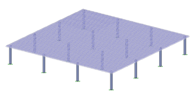
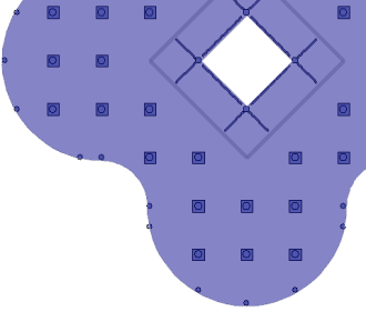
Unlike Beam Supported Floors, Concrete Floor Slabs have no restrictions on the shape or size of the floor's perimeter (edge). This allows for complete flexibility in designing floor slabs with curved edges, or protruding balconies. Modeling a floor system such as the one below would be difficult or impossible as a Beam Supported Floor. Openings may also take any shape, and do not require beams around their perimeter.
The concrete floor slab must be supported by vertical supports. These can be modeled as either columns or walls. In cases where punching shear is an issue, columns may include an integrated Shear Cap, which is essentially a thickening of the slab near the column. The interior columns in the image above show square Shear Caps, while the perimeter columns do not.
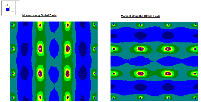
The weight of the floor slab (which is usually significant) is combined with the superimposed vertical (gravity) loads, and is attributed to the supports based on the slab's stiffness. Unlike Beam Supported Floors, where the load on a support is a direct function of the support's tributary area, in Concrete Floor Slabs a finite element analysis (FEA) is undertaken in order to determine which portion of the load travels to which supports. In FEA the majority of the load will always travel along the route of greatest stiffness. Note the uniform slab below, with uniform loading and regularly spaced supports:
The bending stress contours of the slab show flow of forces in two directions with the slab experiencing the greatest tensile stresses (color coded in pink) at the supports. There are regions in the slab with virtually zero moment (color coded in greens). In order to optimize the design of the reinforcement over the areas of high moment, the design strip method is used in both directions.
The quantity of rebar required in a given area of the slab is proportional to the bending stress in that area and prescribed minimums. Therefore, locations with higher bending stress such as the area directly between columns require more rebar than locations with lower bending stress such as the space in the "middle" of the four columns on the images above. As part of their Equivalent Frame Method, the ACI code recommends dividing reinforcement design into "strips":
Column Strips run directly from column-to-column in each of two orthogonal directions. In slabs where the rebar is laid out orthogonally there are two nominal directions (North-South and East-West) that column strips run along. This means that the direction of the rebar in the North-South column strips is perpendicular to the direction of the rebar in the East-West column strips, regardless of the direction of True North. By using this compass terminology it is easy for the user to keep track of which set of rebar is which. Column Strips are assigned a width which is intended to capture the area of the slab with the highest bending stress, and thus the need for the most reinforcement.
Middle Strips run both parallel to, and adjacent to Column Strips. They also use the North-South, East-West terminology for organization. The middle strips fill in the gaps between column strips, to ensure that the areas of the slab with little or no bending stress still receive a minimum of reinforcement.
By dividing the slab into Column Strips and Middle Strips the designer can ensure that the entire slab is receiving adequate reinforcement, and that reinforcement is placed only where it is needed. Beware that any area of the slab which is not part of a column strip or middle strip receives no reinforcement design.
RISAFloor ES gives the user flexibility for rebar placement. This flexibility is necessary to achieve adequate designs for diverse building designs where supports may not be regularly spaced, or orthogonal. This overcomes the limitations of the ACI Direct Design method, which is predicated on simplified building layouts that make hand calculations possible. In RISAFloor ES, rebar design is performed based on the hierarchy explained below. For easier comprehension an example slab as shown below will be used to illustrate each element in the hierarchy.
Support Lines are drawn by the user, and are used to define a line of supports for the slab that run along a nominal North-South or East-West direction. Support Lines should run along the shortest possible path between supports. Adjacent support lines should be approximately parallel, however complex support configurations can make this difficult to achieve. Note that support lines may cross or terminate at walls (in addition to columns).
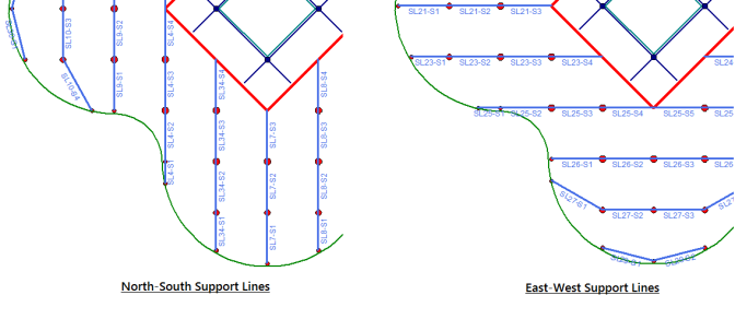
Each Support Line is divided into Spans. RISAFloor ES automatically creates the spans for each support line, based on the supports which the Support Line crosses. Each Span is intended to run from support-to-support, although spans may also dead-end into a location other than a support, such as a slab edge. In the image below, Support Line 26 (SL26) which is nominally an East-West Support Line is split into four spans (Span 1, Span 2, etc.) which are labeled SL26-S1, SL26-S2, etc.

Per the Equivalent Frame method, each Span is divided into three Design Strips: Middle Strip- Left, Column Strip, Middle Strip- Right. The Column Strip is approximately centered on the Support Line. The Middle Strips (Left and Right) fill in the gaps between the Column Strips of adjacent Spans. Each Span has its own Middle Strips, so the Middle Strips of adjacent spans butt up against each other.
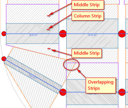
The Middle Strip- Left is the strip to the left of the Support Line. In the example above, Support Line 26 (SL26) was drawn left-to-right, so the "Left" strip is the upper strip (as that would be the Left direction when looking along the line the Support Line was drawn). Note that the Middle Strip- Right is tapered so that it does not overlap with the Middle Strip- Left of Support Line 27, Span 1 (SL27-S1). Also note that there is a location where multiple strips overlap. In locations where design strips overlap the required rebar for all of the overlapping strips is used. This results in a conservative design.
The Column Strip width is automatically calculated, and is based on the distance to adjacent Support Lines or Slab Edges. In the example above the column strip for Span 2 is wider than the column strip for Span 1. Click here for the exact description of the Design Strip Width equations. The Design Strip width is calculated with the intention of capturing the highest moment demands in the column strip. The most ideal width would be the bound by the zero shear however the widths are currently only based on the Equivalent Frame Method.
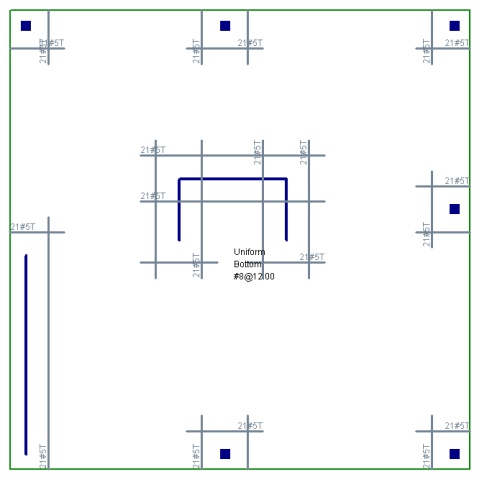
There will be top reinforcement designed over the supports due to the tension at the top of the slab (positive moment). The gap between design strips of adjacent spans (shown as empty white space in the image above) is addressed by running the Top Rebar continuously through the column (or through the gap in the case of Middle Strips). RISAFloor ES automatically does this as part of the rebar design. The bottom reinforcement is designed with the same spacing over the entire design strip to resist the tension at the bottom of the slab (negative moment).
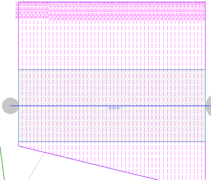
Each Design Strip is automatically divided into Design Cuts. A Design Cut is a two dimensional cut through the thickness of the slab, perpendicular to the Support Line. The width of the cut is equal to the width of the Design Strip. In the image below, the Design Strips of Support Line 26, Span 1 (SL26-S1) contains 50 Design Cuts. These Cuts are shown as dashed pink lines running perpendicular to the Support Line. The Cuts are numbered starting at the left as Support Line 26, Span 1, Cut 1 (SL26-S1-X1) through Cut 50 (SL26-S1-X50). In this example, the Design Cuts for the Middle Strip-Left and the Column Strip have a uniform width, but the Design Cuts for the Middle Strip-Right have varying width since the Middle Strip-Right is tapered.
At each Design Cut, RISAFloor ES sums up the total forces across the Cut, as determined by FEA. The total shear for the Cut is used to perform a one way shear check. The total bending moment across the Cut (taken as the bending moment about the Cut axis) is used to determine the required amount of rebar at the Cut location. All this analytical and design information is presented in the Design Cut Detail Report.
RISAFloor ES calculates the rebar requirements for each Design Cut and uses that to determine the required rebar for each region within the Design Strip, including where the bars must start and terminate along the length of the strip. With the design of rebar for all three strips, the required placement of rebar for each Span is determined. To address the bending at supports, the rebar for each Span is matched to the rebar for adjacent Spans so that the top bars can be run continuously. Compatible designs for all adjacent Spans result in an overall rebar design for the entire Support Line.
If all of the Support Lines for a given direction (such as nominal East-West) are arranged such that their Design Strips butt up against each other then all of the required rebar for the slab is calculated for that direction by RISAFloor ES. If the same is true for the other nominal direction, and if there are no significant gap areas (where no Design Strip from either direction is present) then RISAFloor ES provides you with a complete rebar design for the entire slab, sufficient to meet all code requirements.
Using the User Defined Rebar option in RISAFloor ES gives the user a simple option to check rebar pattern for the entire slab. This option allows the user to set a regularly spaced top and bottom rebar to check whether it meets code requirements. You can set this method from the start or flip back and forth to the Design Strip Method. For a full step by step, see User Defined.